This is the third blog post in a series that discusses the advantages of working on concrete projects in a BIM process for structural engineers.
Before we dive in, let’s quickly review the four benefits of BIM for engineers:
- Combines the versatility of 2D documentation with the higher level of fidelity and accuracy of 3D modeling of steel reinforcement and concrete accessories, with minimal effort to produce both.
- Allows users to design and detail with rebar clash prevention in mind to reduce clashes both in the preconstruction and site execution project phases.
- Enables the transition from design to detailed models while respecting both perspectives, following local code requirements, and automating the process of making changes so they are less disruptive to the design process.
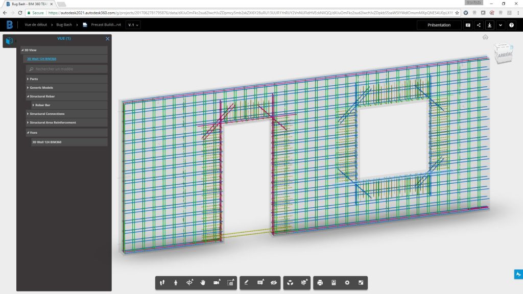
- Increases transparency and quality of the model information being used from bidding to procurement by not only providing quantifiable information, but also enabling access to it in collaboration friendly environments.
This post will focus on the “how” of benefit three.
Benefit #3: The BIM-centric concrete solution enables the transition from design to detailed models while respecting both perspectives, following local code requirements, and automating the process of making changes so they are less disruptive to the design process.
Coordinating the design intent model with the detailed model has always been a factor of “bureaucracy,” since historically, structural engineers work with different software than other project stakeholders. Tools to import and export various file formats across software produced by different companies have been used for some time, but we believe simplicity and precision should be a key factor for coordination and will ultimately lead to a strong and reliable behavior of any structure during its lifecycle.
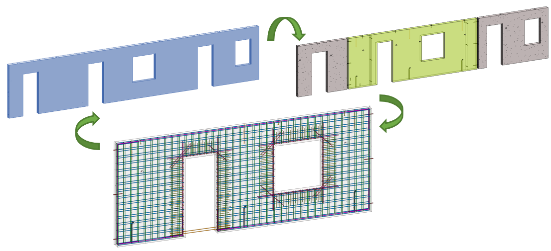
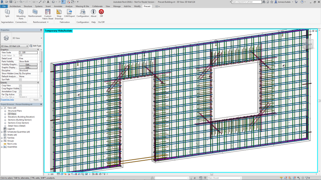
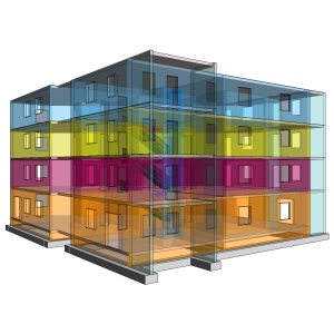
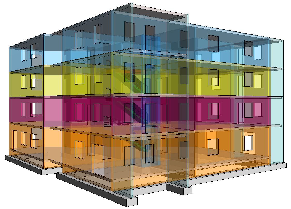
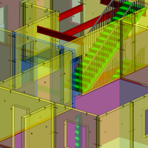
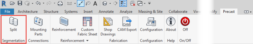
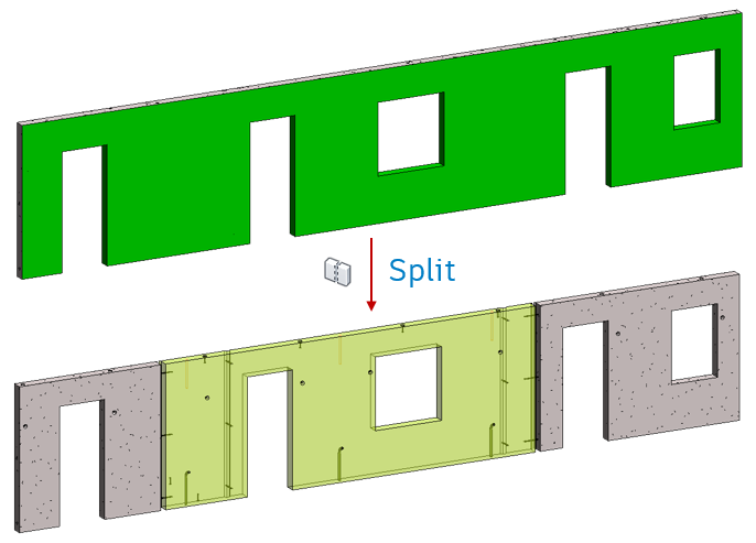
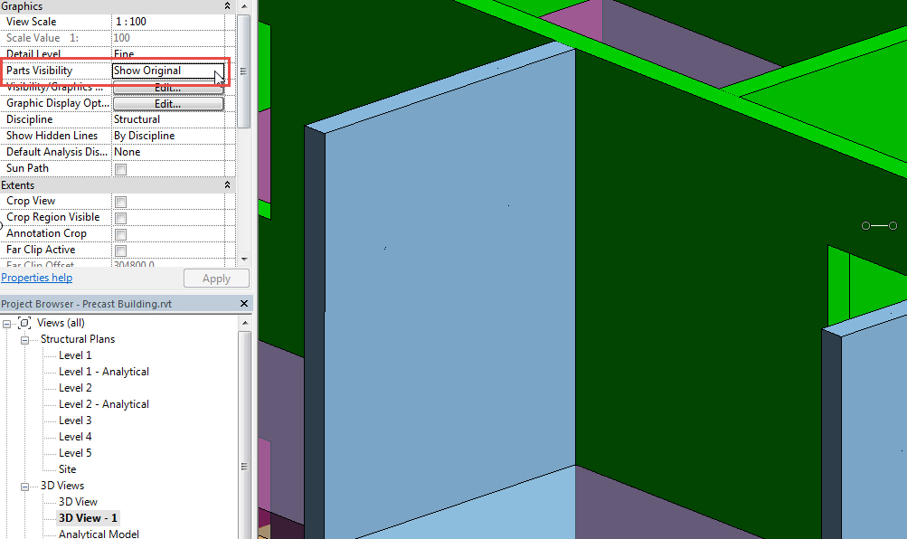
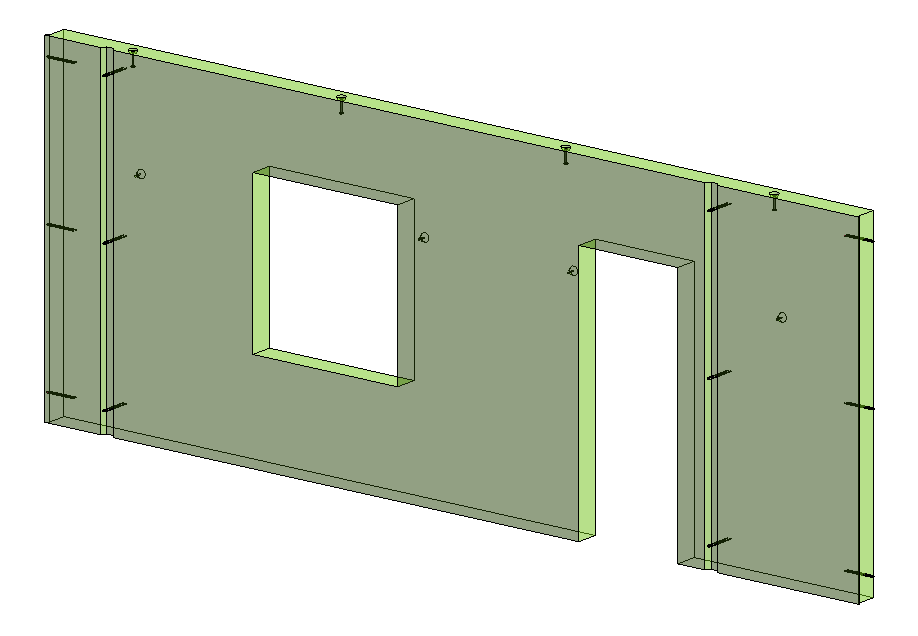
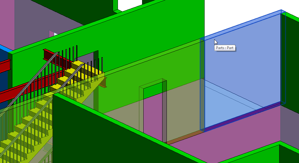
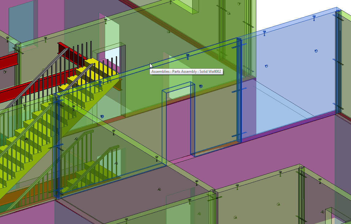
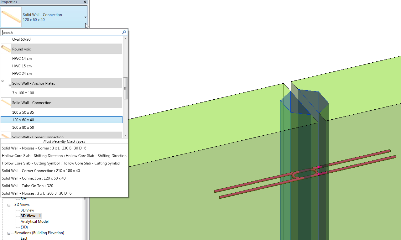
Take, for example, a precast concrete wall. Its length and height are dictated by its place in the building. Segmentation is dictated by engineering, architectural, or fabrication requirements, and its reinforcement is determined by the structural engineer.
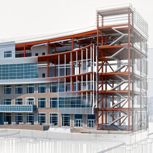
![]()
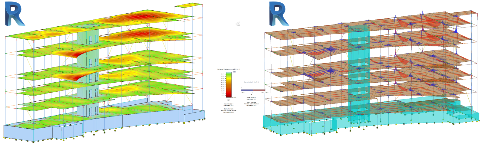
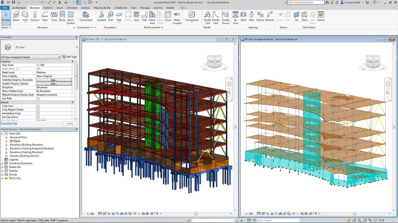
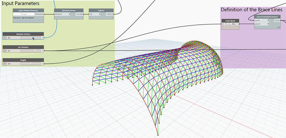
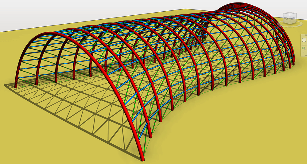
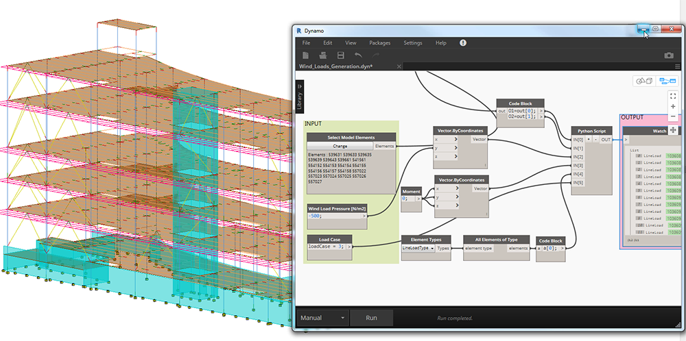
Revit-model-driven structural-analysis
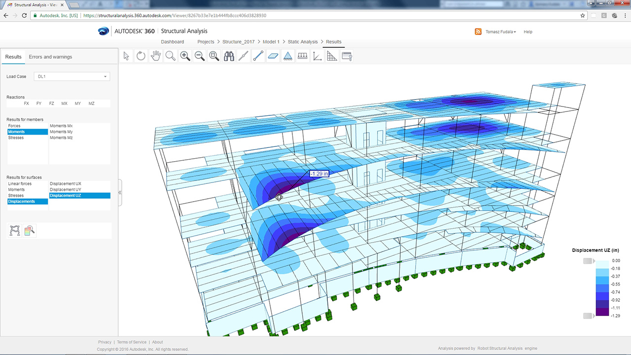
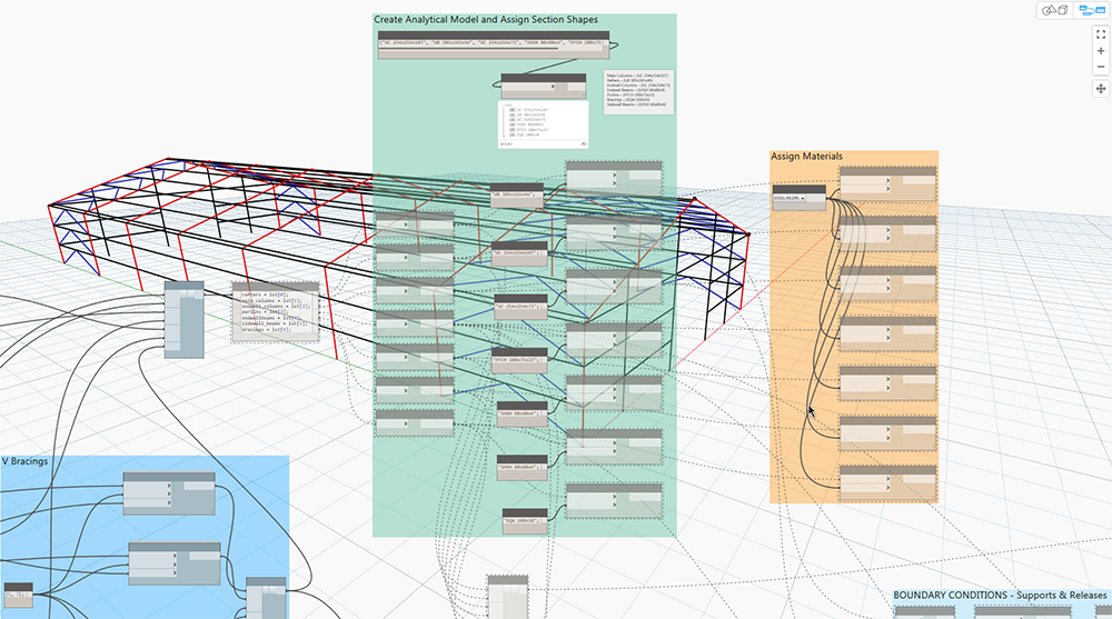
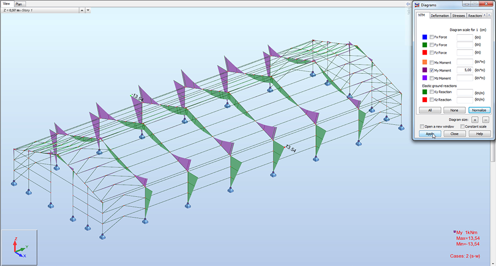
Let’s assume a conceptual model is received from the architect. The structural engineer creates the analytical model and structural system. Revit has multiple tools for defining and editing the analytical model, or the model can be exported to various analysis software that are interoperable with Revit – including Robot Structural Analysis Professional – to perform structural analysis. The results can then be imported into Revit and reviewed to understand the impact of various design changes.
![]()
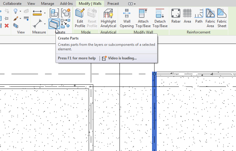
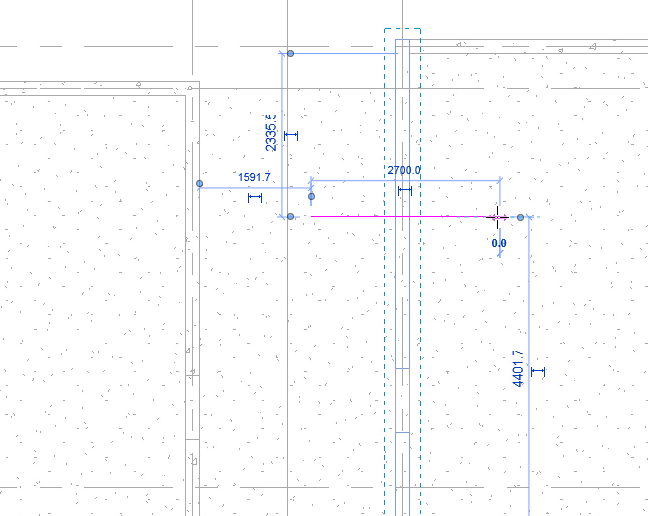
With the results now available in the Revit model, the rebar definition can begin. There are two approaches to this process – one for EMEA and the other for AMER.
Firstly, the structural engineer analyses the efforts and proposes reinforcement patterns, a practice typically encountered in North America. The engineer can use engineering schedules or place tags in 2D or 3D views that reference concrete elements and reinforcement patterns. Secondly, rebar can be determined more directly by structural analysis results, while respecting local design codes, a method usually embraced by European countries.
The beauty of Revit is that it allows for both approaches, enabling all structural engineers to work in a BIM environment connected to architects, MEP engineers, and the extended project team.
Code-driven automatic generation of reinforcement
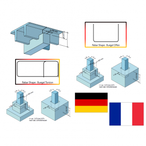
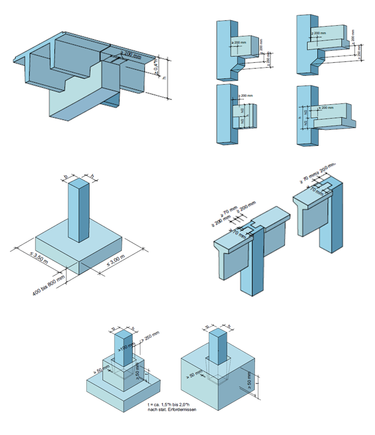
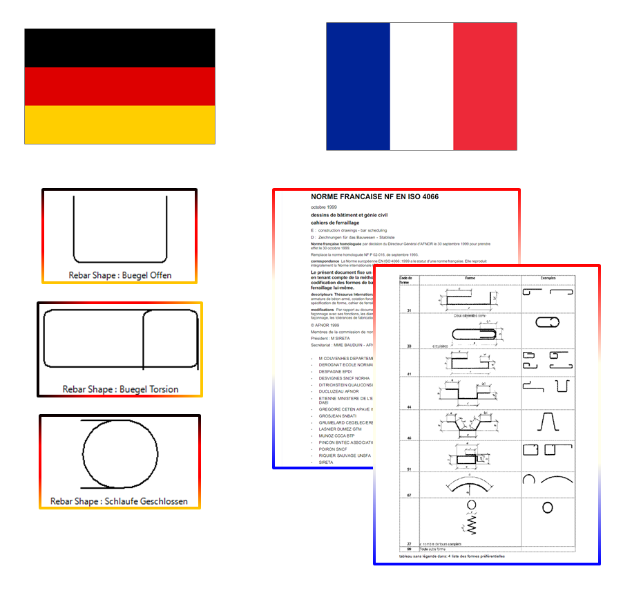
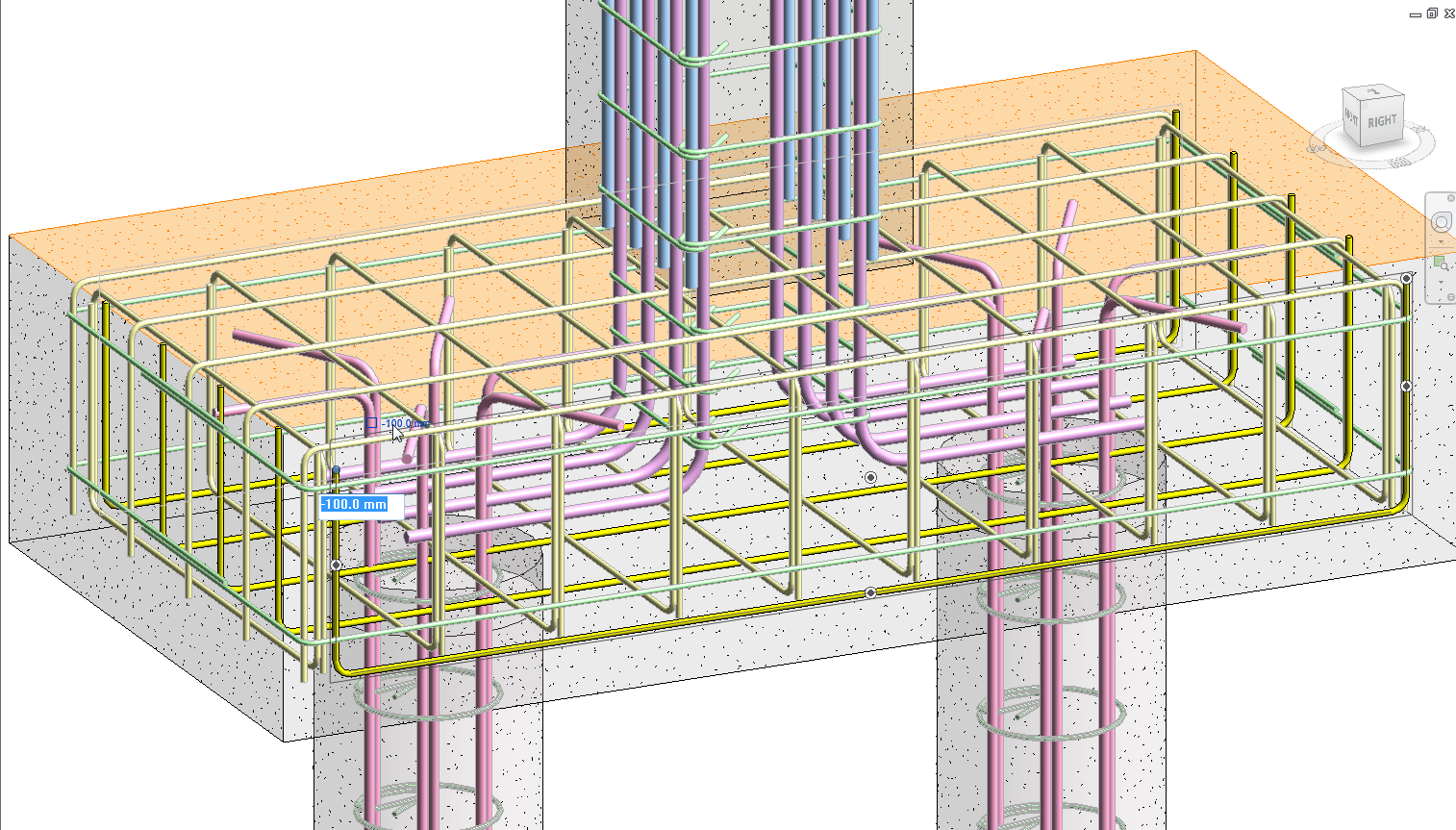
With the “results packages” in the BIM model, code design tools can drive the automatic generation of reinforcement. Multiple types of concrete elements can be reinforced following the engineering design standards from various countries and regions.
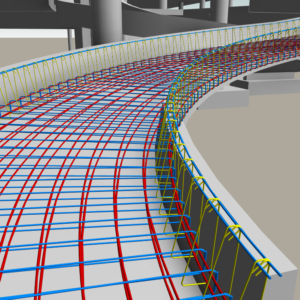
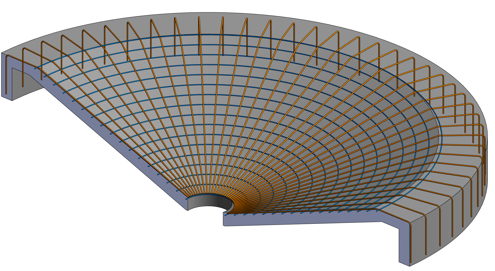
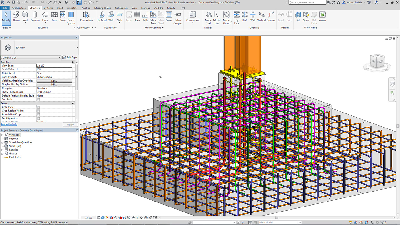
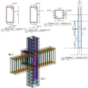
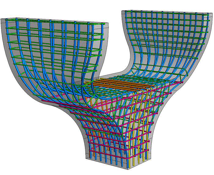
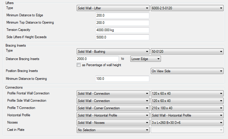
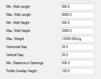
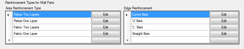
SOFiSTiK Reinforcement Generation (RCG) automatically generates a 3D rebar model in Revit based on structural analysis input, and works with concrete beams, columns, floors, walls, and slabs. It follows the defined rules to generate the reinforcement to meet the required reinforcement criteria. Respecting various country or company standards can be done by controlling the rules files. Once the reinforcement is generated, it can be manually edited.
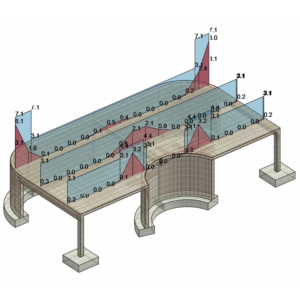
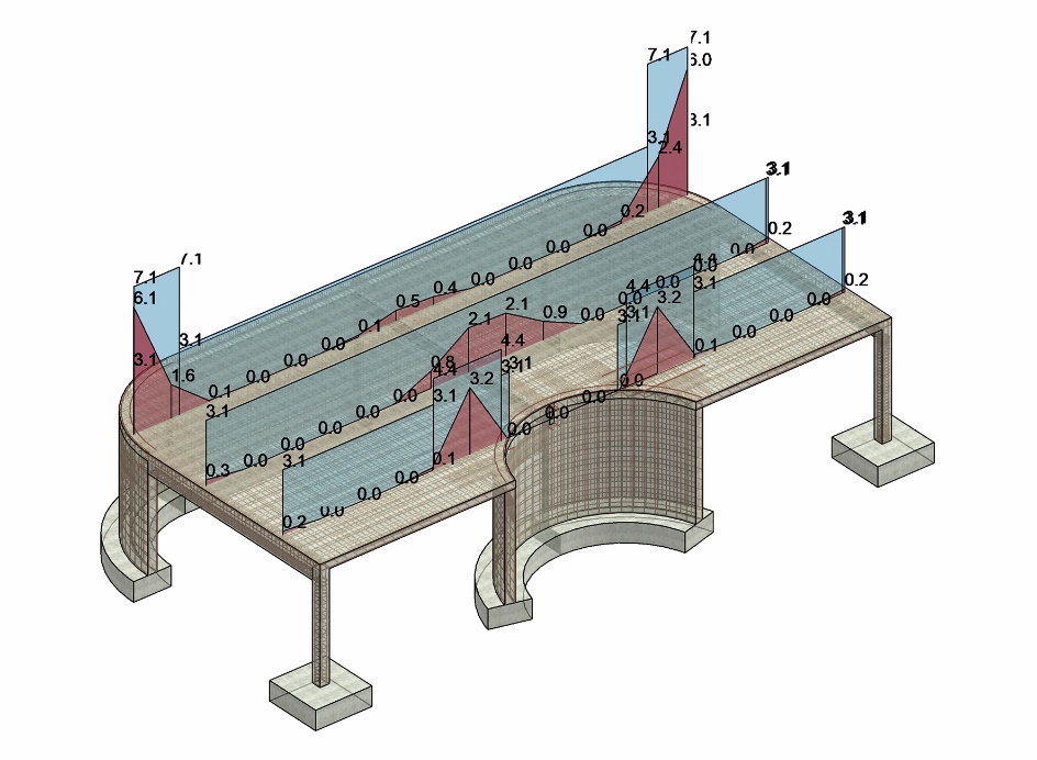
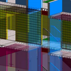
RCG offers real-time checking of the reinforcement directly in Revit 3D views. Using the “Check” command, the required and existing reinforcement in a framing element can be compared. If the reinforcement is adjusted, the diagrams react instantly, giving precise feedback to the engineer about how to optimize the reinforcement patterns.
![]()
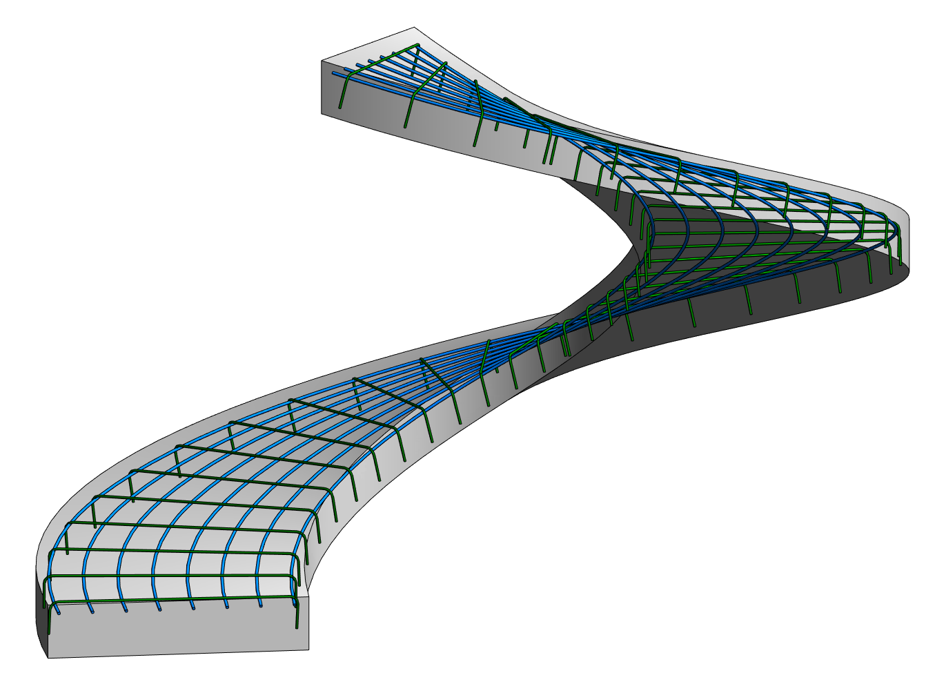
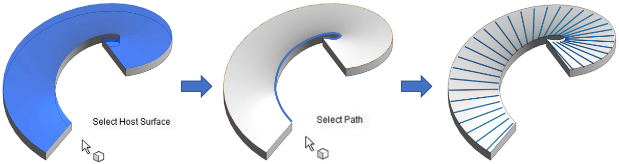
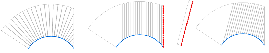
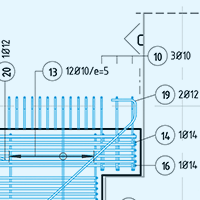
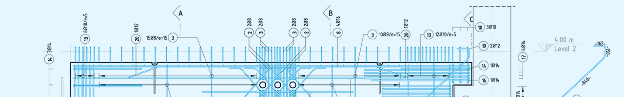
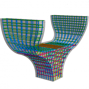
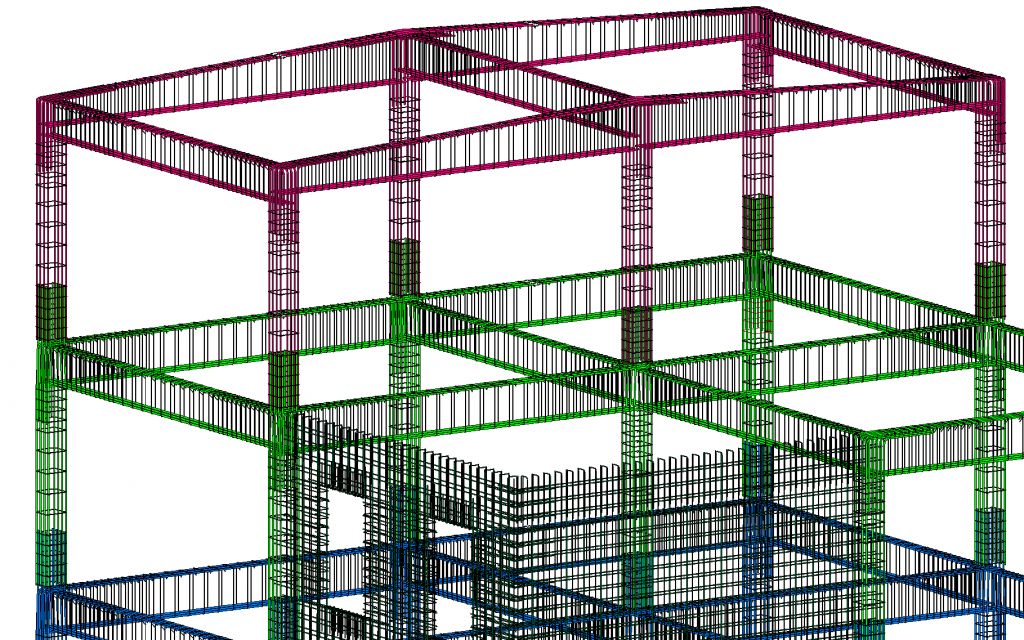
In a similar manner, the “Check section” command compares the existing reinforcement in user-defined sections of surface elements against the required reinforcement.
![]()
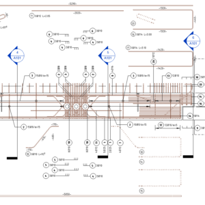
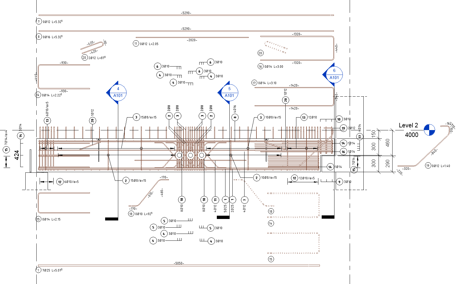
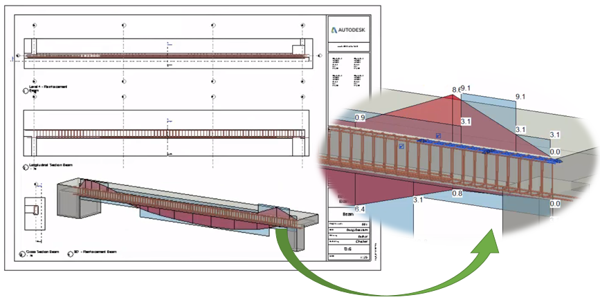
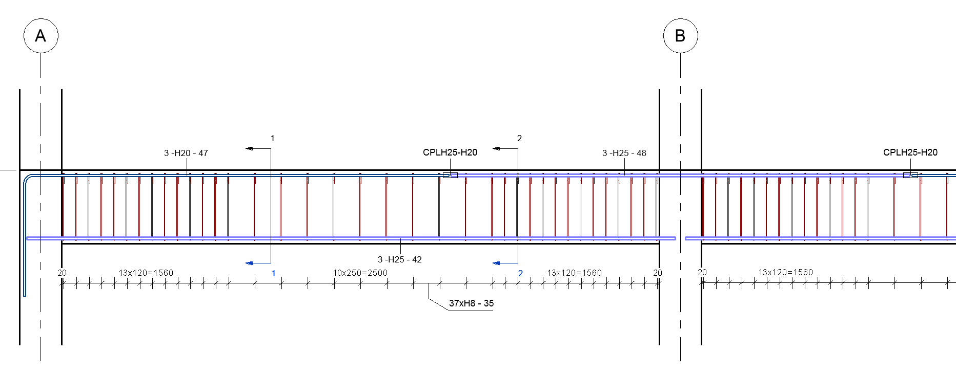
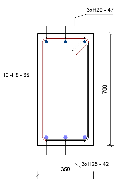
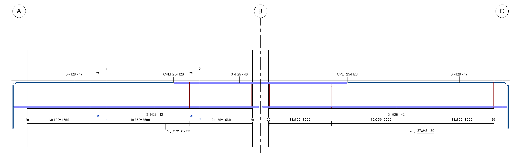
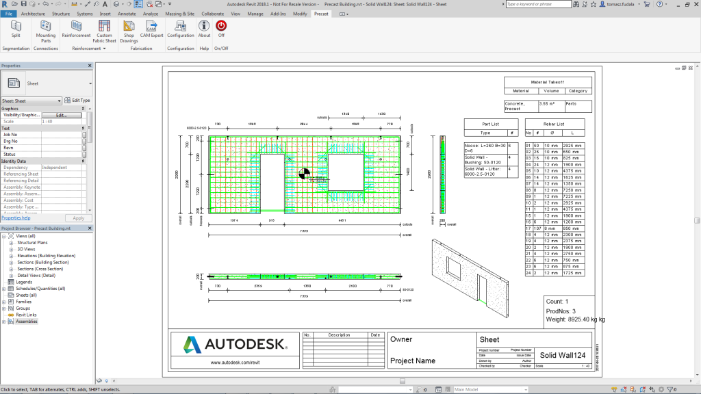
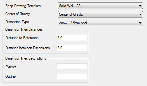
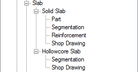
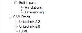
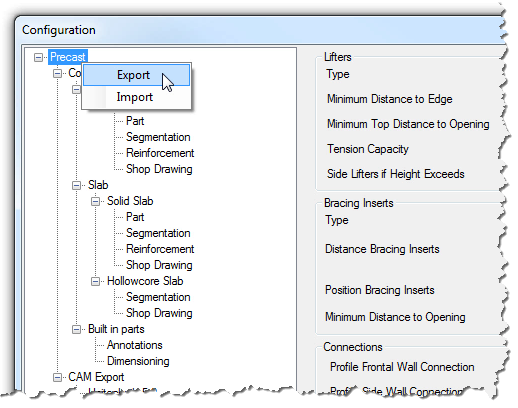
Once the rebar modelling is complete, detailing can begin. To comply with the same standards across this phase of the project, the SOFiSTiK Reinforcement Detailing tool can produce customized shop drawings and bar bending schedules.
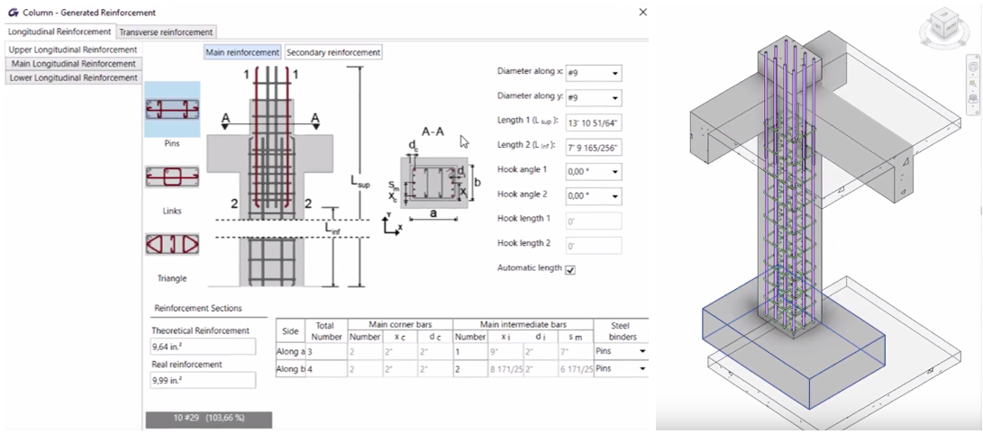
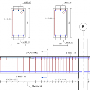
Graitec Reinforced Concrete BIM Designers is another powerful tool that leverages Revit results packages to generate reinforcement in single-span and continuous beams, columns and isolated foundations. It is compliant with Eurocode 2, US ACI 318-14, and Canadian CSA standards. The various settings allow the use of specific bar diameters and other constructability rules, like the maximum number of bars to be placed in a concrete element according to its width.
![]()
The tool also calculates a group of identical elements simultaneously so that they have the same rebar cages, based on the theoretical reinforcement envelope for the entire group. There is also the ability to save reinforcement cage templates which can be applied to similar elements and adapt to their new hosts based on predefined rules.
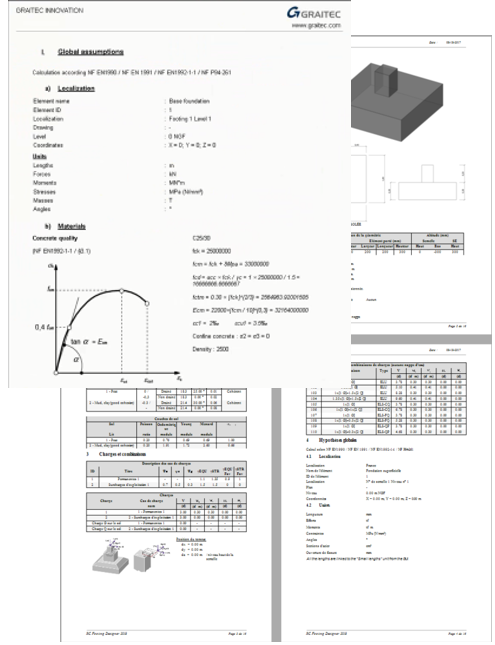
The app also generates engineering design reports. The content of each design report depends on the country-specific template and can be configured by the user. A fully comprehensive design report describes the theoretical formulas and values used in the calculation process according to the country selected, and includes the results and work ratios for each verification.
![]()
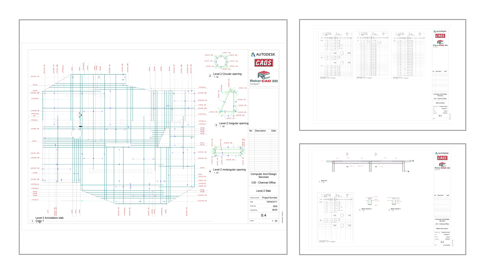
Customizable bar bending schedules and automatic shop drawings based on predefined templates can be created using the app’s dedicated features.
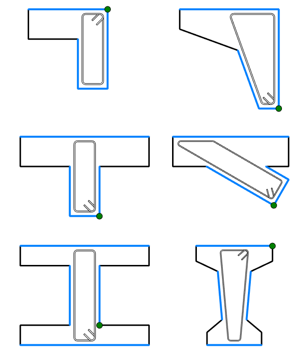
CADS RC3D has been designed to enhance the placement, annotation, and bar marking of rebar in 3D structures. The software provides functionality to create 2D detail drawings and bar bending lists to country standards. Features of the app include:
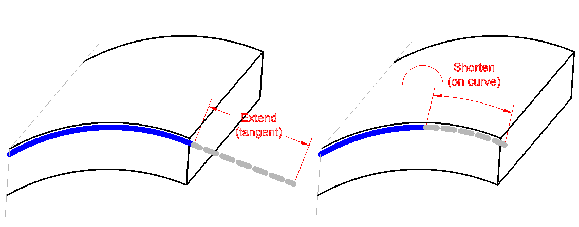
- Annotation functions to detail tapered ranges and mark rebar ends
- Enhanced layering tools to split rebar into zones within a structure
- Editing functions to copy rebar from one structure to another
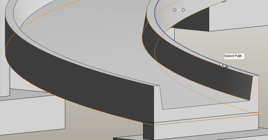
- Path placement functions to allow the rebar to be placed parallel to another rebar in the structure
- Managing the rebar according to assigned structure, release, and drawing sheet
- Custom rebar lists
![]()
One Source of Truth
Given that the above steps can be completed in the same model, it is easy to see the benefit of having one source of truth and using Revit as the single platform for design and detailing.
Since many reviews occur during the design phase, we can expect many changes to the geometry of the concrete elements. Normally, this could lead to significant manual changes to the reinforcement, but because Revit’s reinforcement is constrained to the concrete elements, it means it adapts automatically every time.
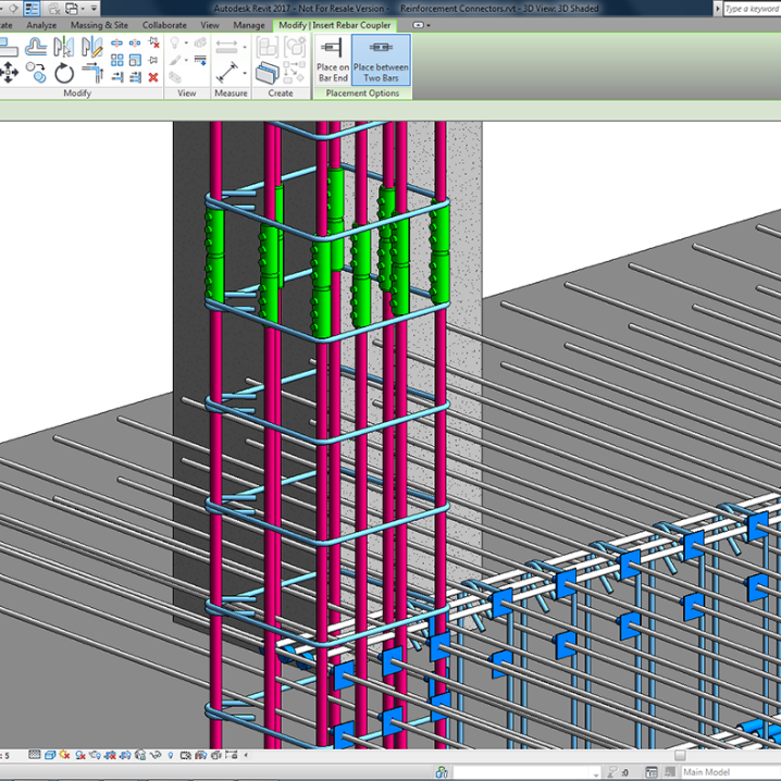
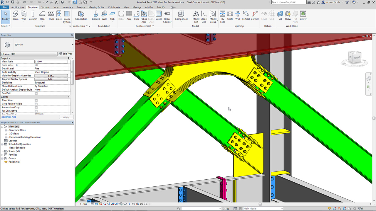
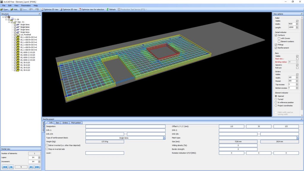
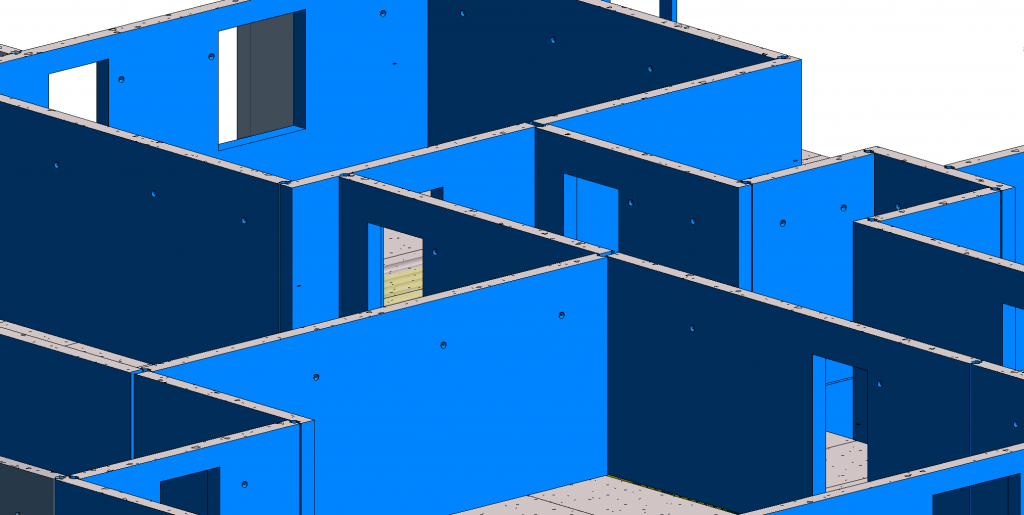
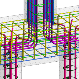
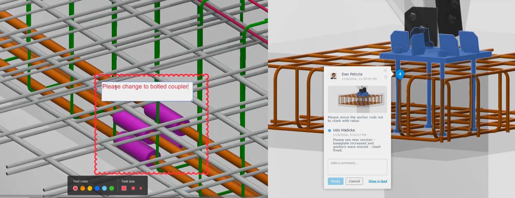
And not only is the rebar in-sync with the concrete structure, it can also be modelled in its finest details to achieve a clash-free model, ready to be sent to fabrication and installed on site.
Having always up-to-date and coordinated structural analysis results, rebar models, engineering design reports, bar bending details, bar schedules, and shop drawings will ultimately lead to successful project delivery.
![]()
To learn more about how customers are using these tools and solving complex challenges, you can visit the Revit Structure Forum and join a community of structural professionals.
The post BIM for Reinforced Concrete – From Design to Detailing in One Model appeared first on BIM and Beam.
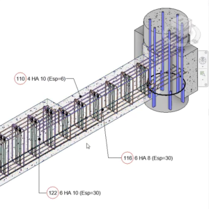
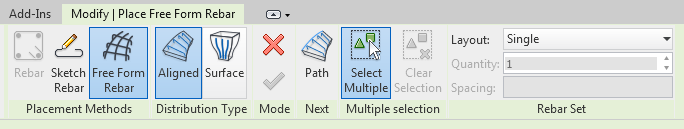
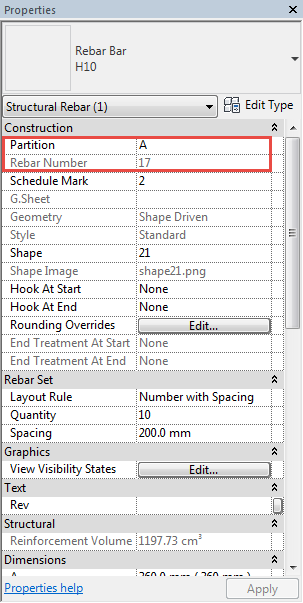
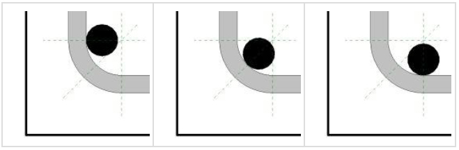
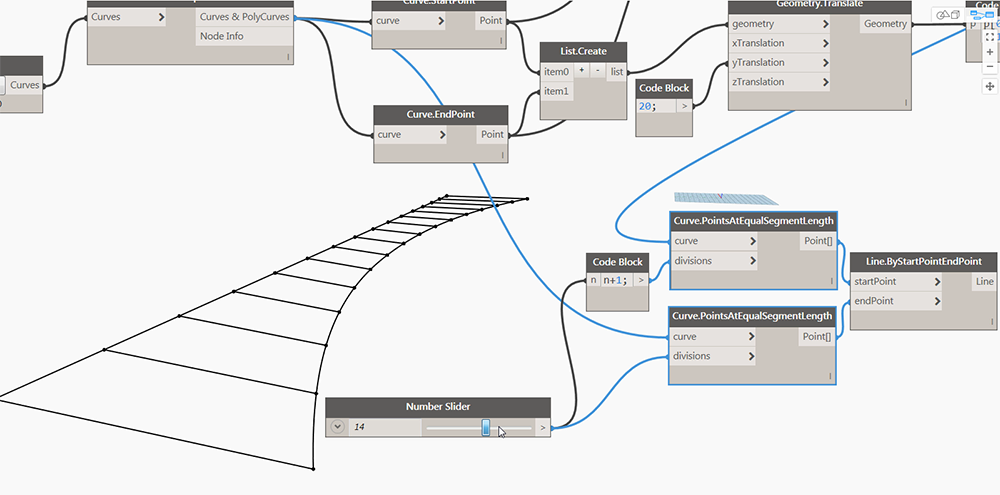
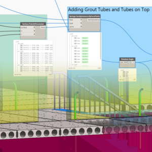
 Rebars are created at the cover distance from the intersection of the references that the Revit user selects. One reference can be made up of one or more structural element faces.
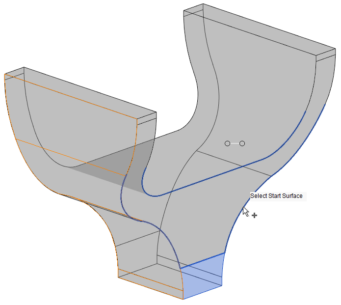
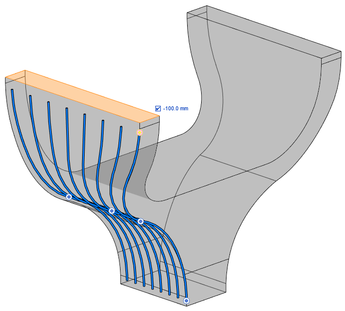
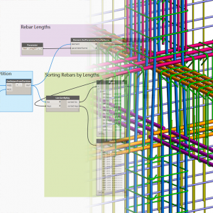
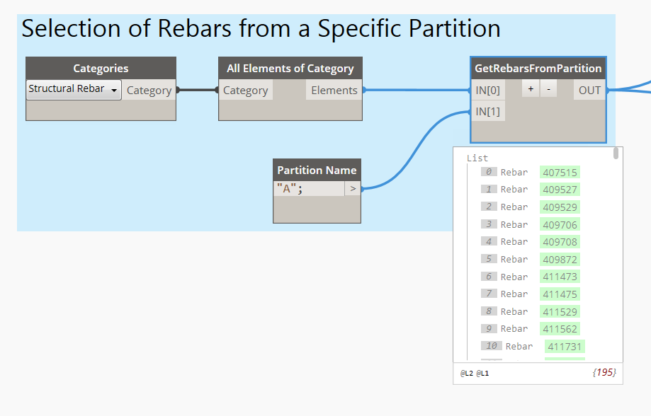
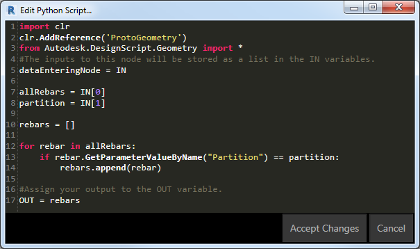


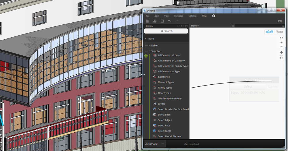
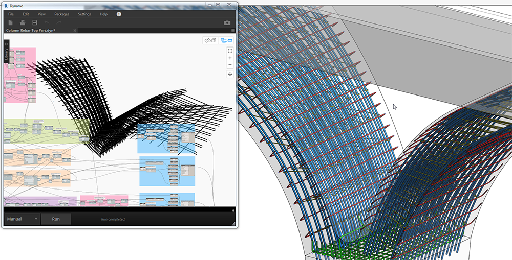


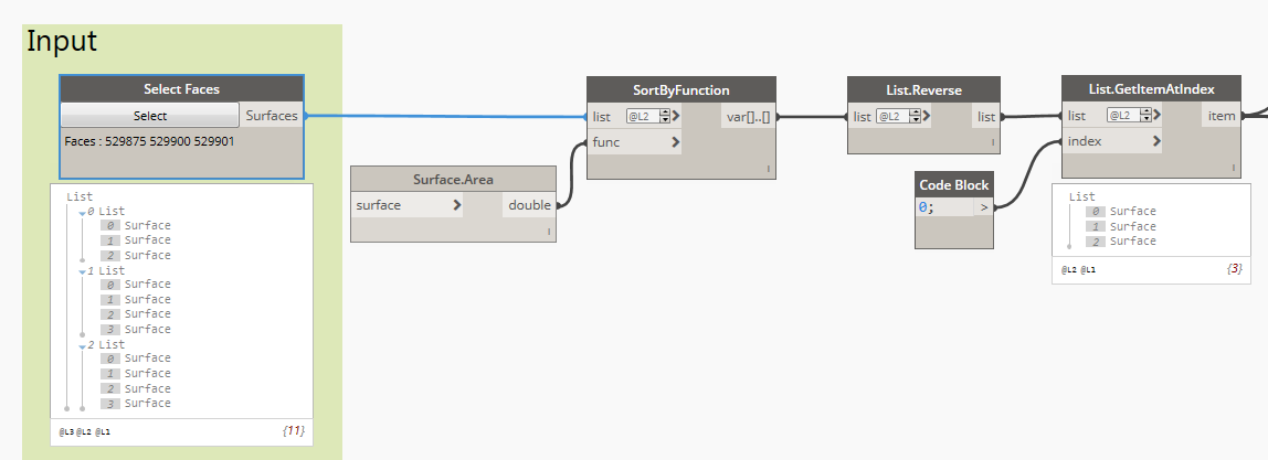
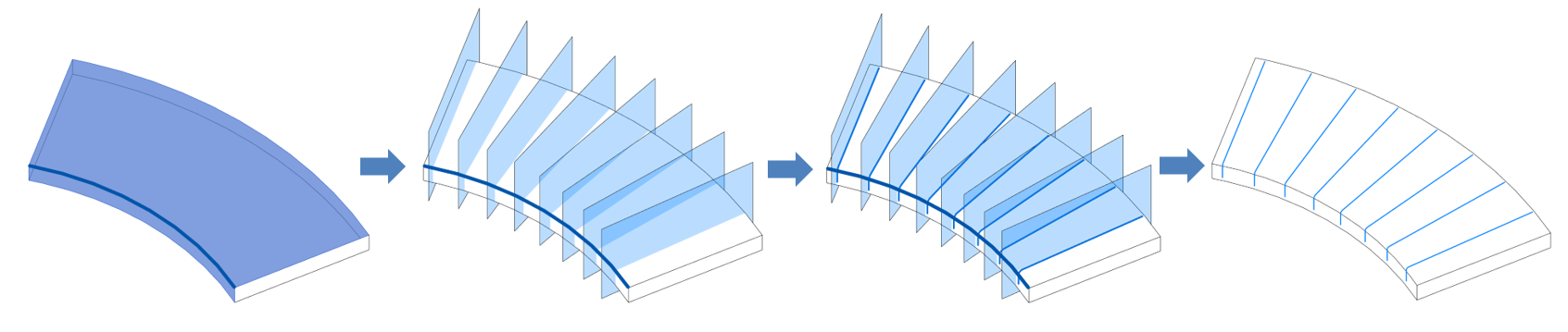
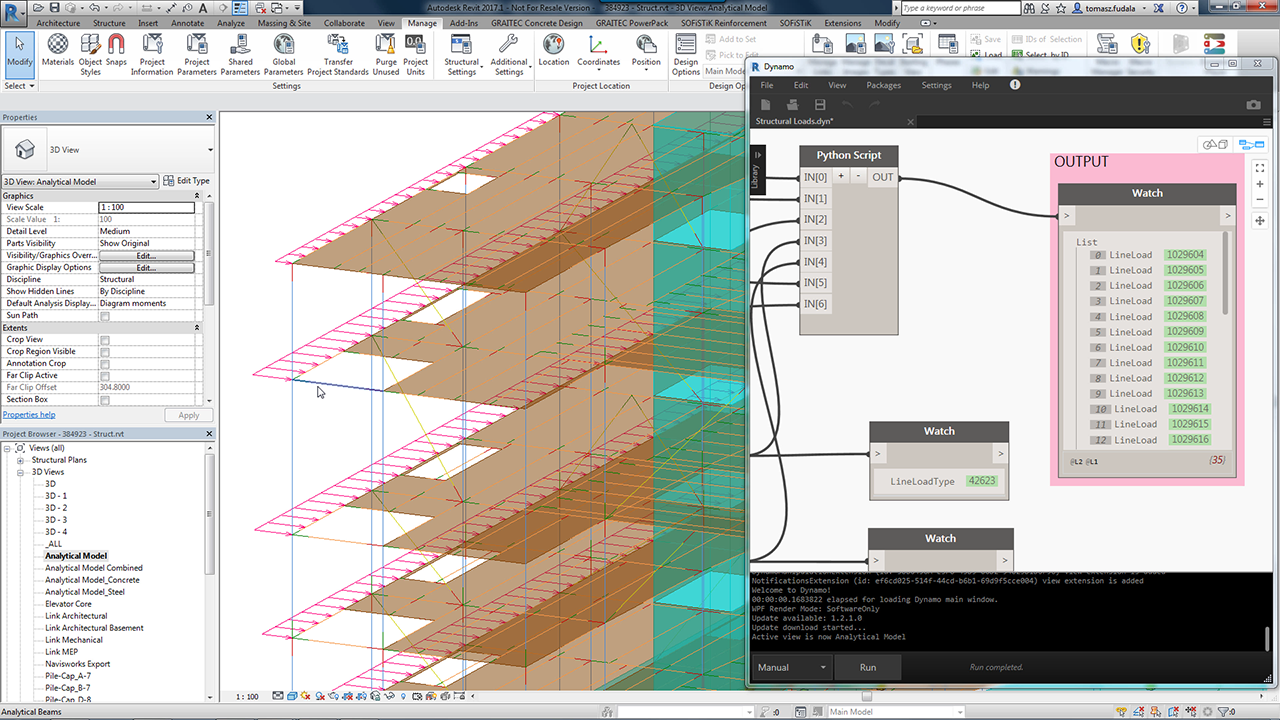
 Let’s have a look inside the Dynamo script. First, I need to retrieve selected faces.